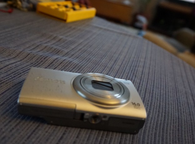
The Canon A4000 is a great tiny camera for flying aircraft applications. It is fairly new, has image stabilization and only weighs about 150grams. At 16MP it has more than enough pixels for its tiny image sensor. Being a Canon, it also works with CHDK which gives a lot of flexibility for automating and controlling the camera. Due to this, it is a pretty good candidate for conversion to a Near-IR camera. I had read online that it was a challenging camera to convert but it actually wasn’t bad. Heres a step by step.
What you’ll need:
- Tiny phillips screwdriver – Not sure what number it was I was using but only one size is needed and it is the same size as the screws on the outside of the case.
- Some tiny flatheads – For picking the epoxy and prying.
- Canned air (highly recommended)
First step is to open the case. On this camera, you have to take off both halves of the case which clamshell around an inner frame. You remove six screws, two on each side and two on the bottom.

Then you remove the front face by swinging it out from the bottom. The back face then pulls off with a little wiggling.


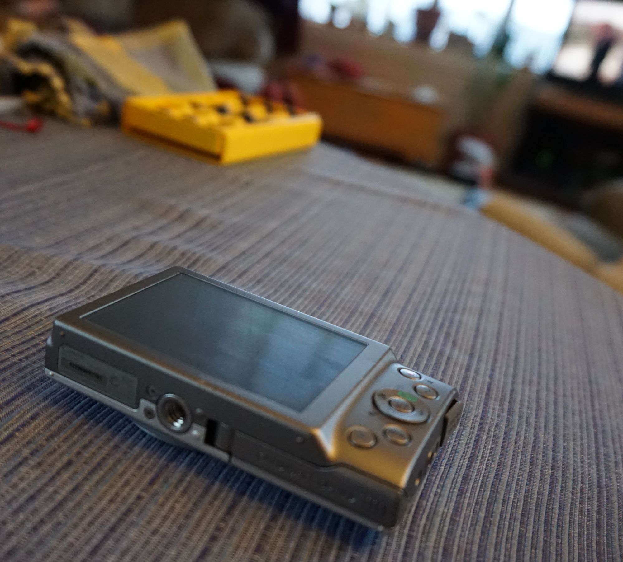
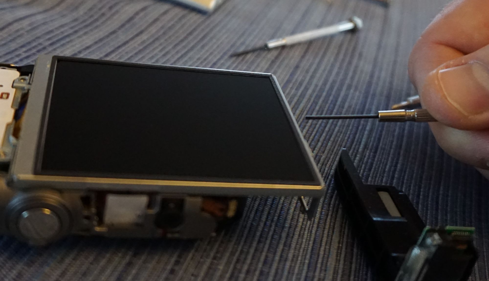
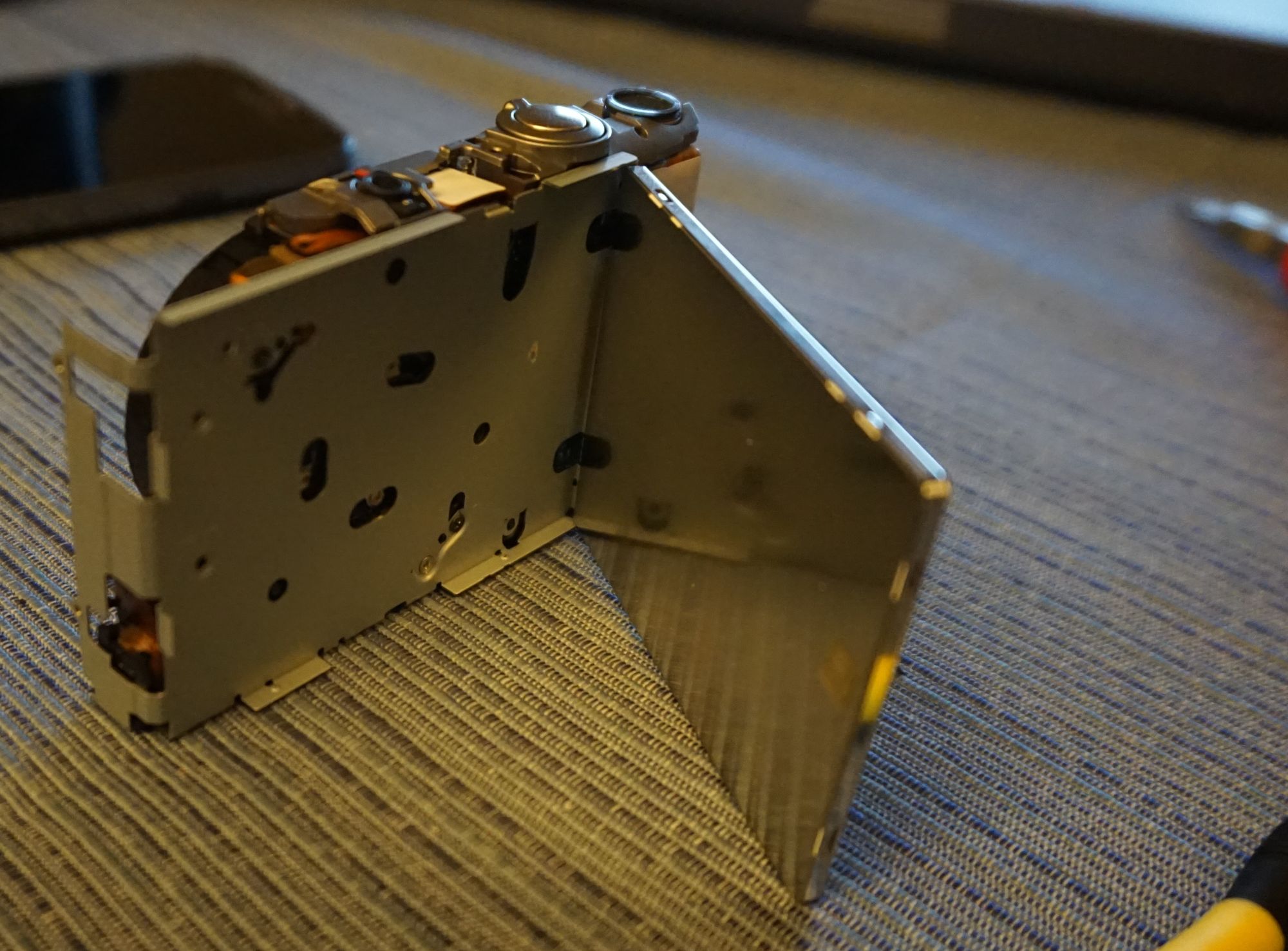
Second step is to swing out the screen. It is attached with a little piece of adhesive tape to the metal bracket on the back. Insert a screwdriver between the screen and the bracket and it should pop away, giving you access to all the screws. (Note that I had already removed the flash here… got ahead of myself!)
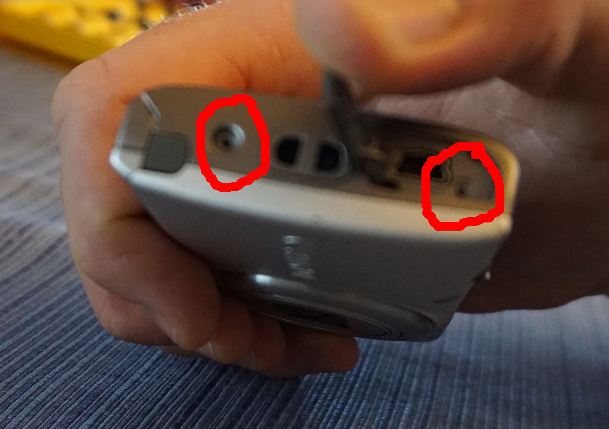
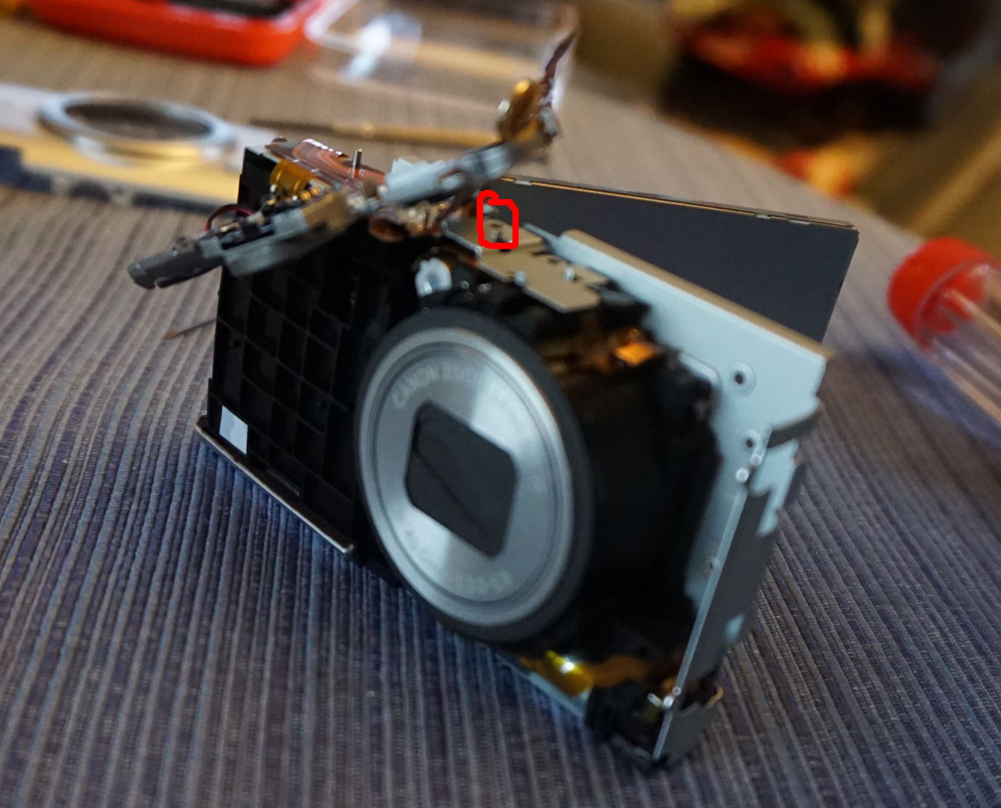
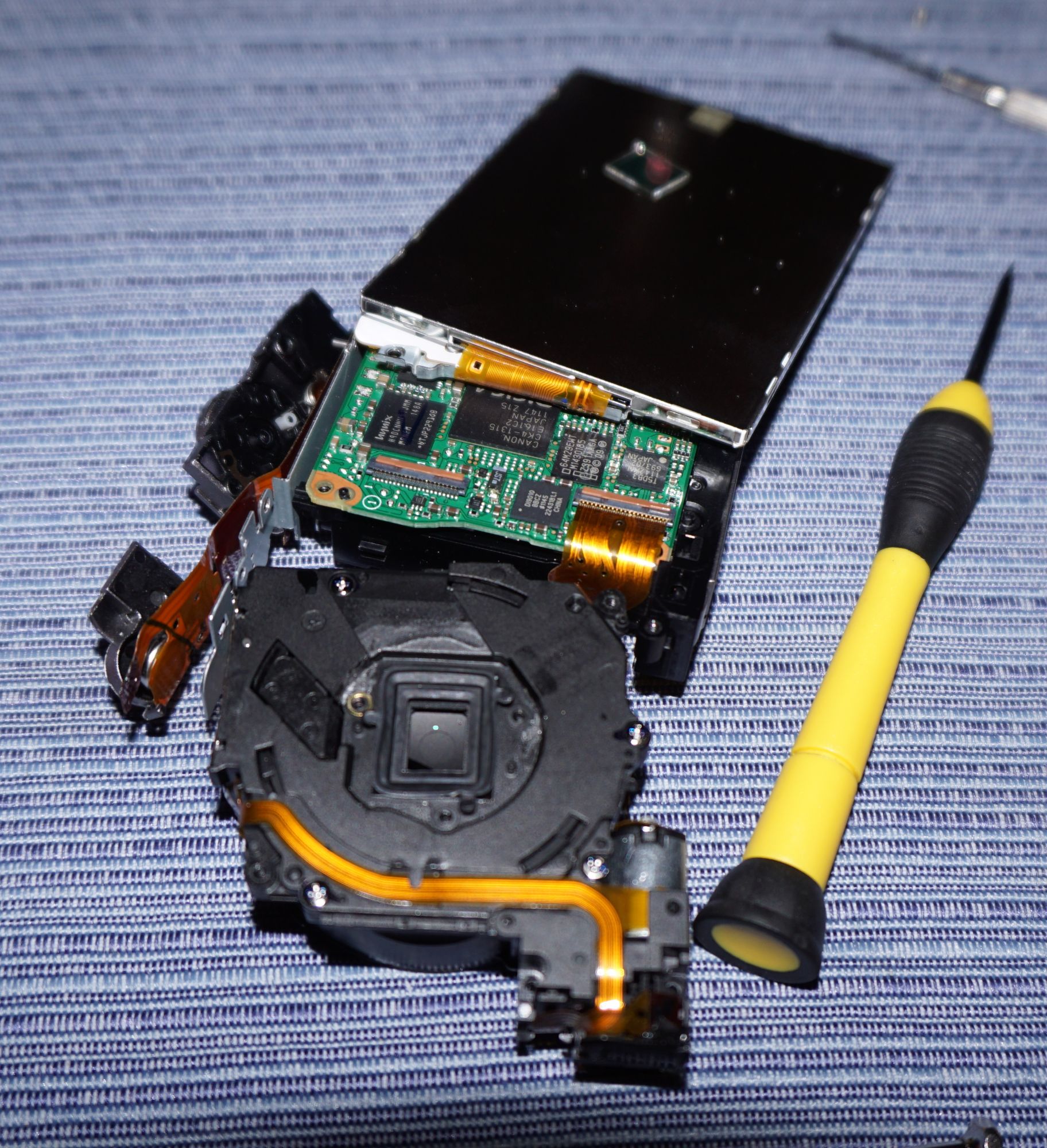
Once the screen is swung out, it reveals a huge number of screws underneath. First you should remove the flash unit. Carefully unlatch the flex connector accessible from the top which connects to the flash. Then remove the screw circled in green below. The flash assembly will come right out. After this, unlatch the button assembly on the top of the camera, and carefully pry up the flex circuit which contains the power button. There is a single screw under there you must remove. In addition to this one, remove all the others circled in red below. Remember where the two black ones and two long silver ones go (on the back of the metal bracket into the lens assembly). The others are all very short. Once all these are removed, you can carefully remove the steel bracket under the screen.
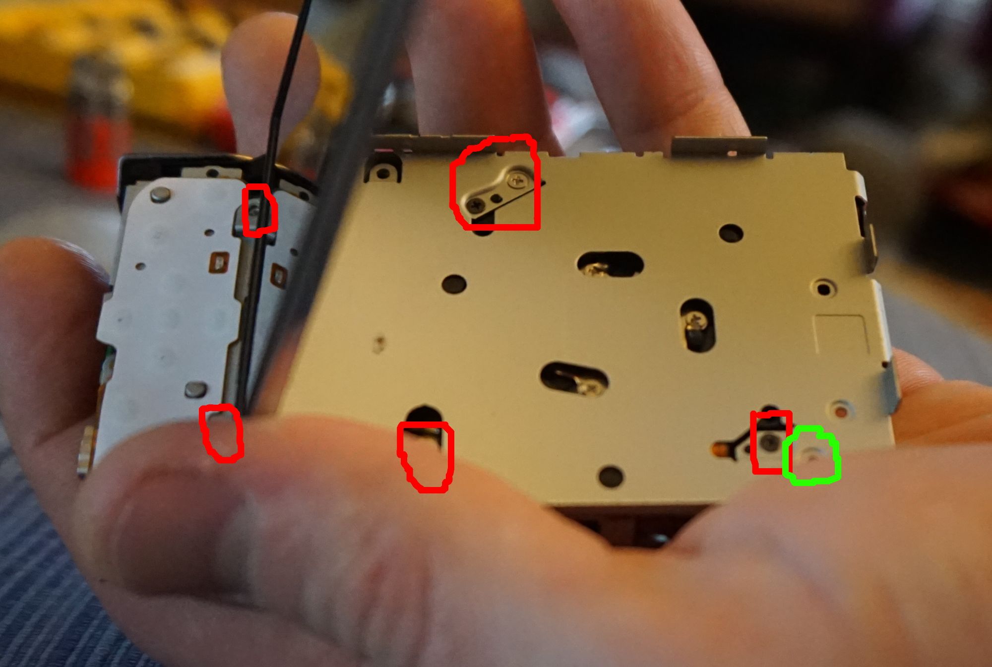
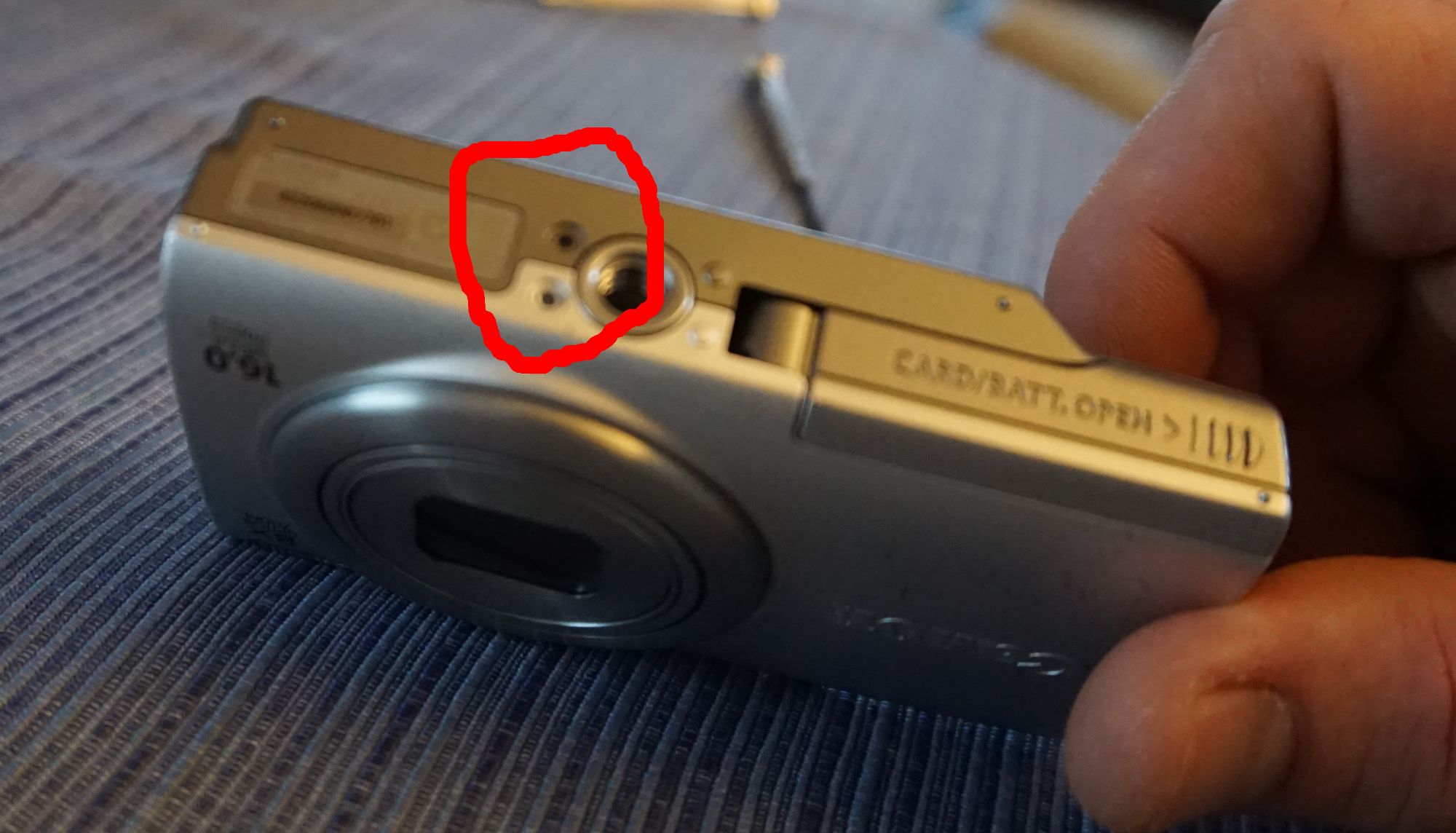
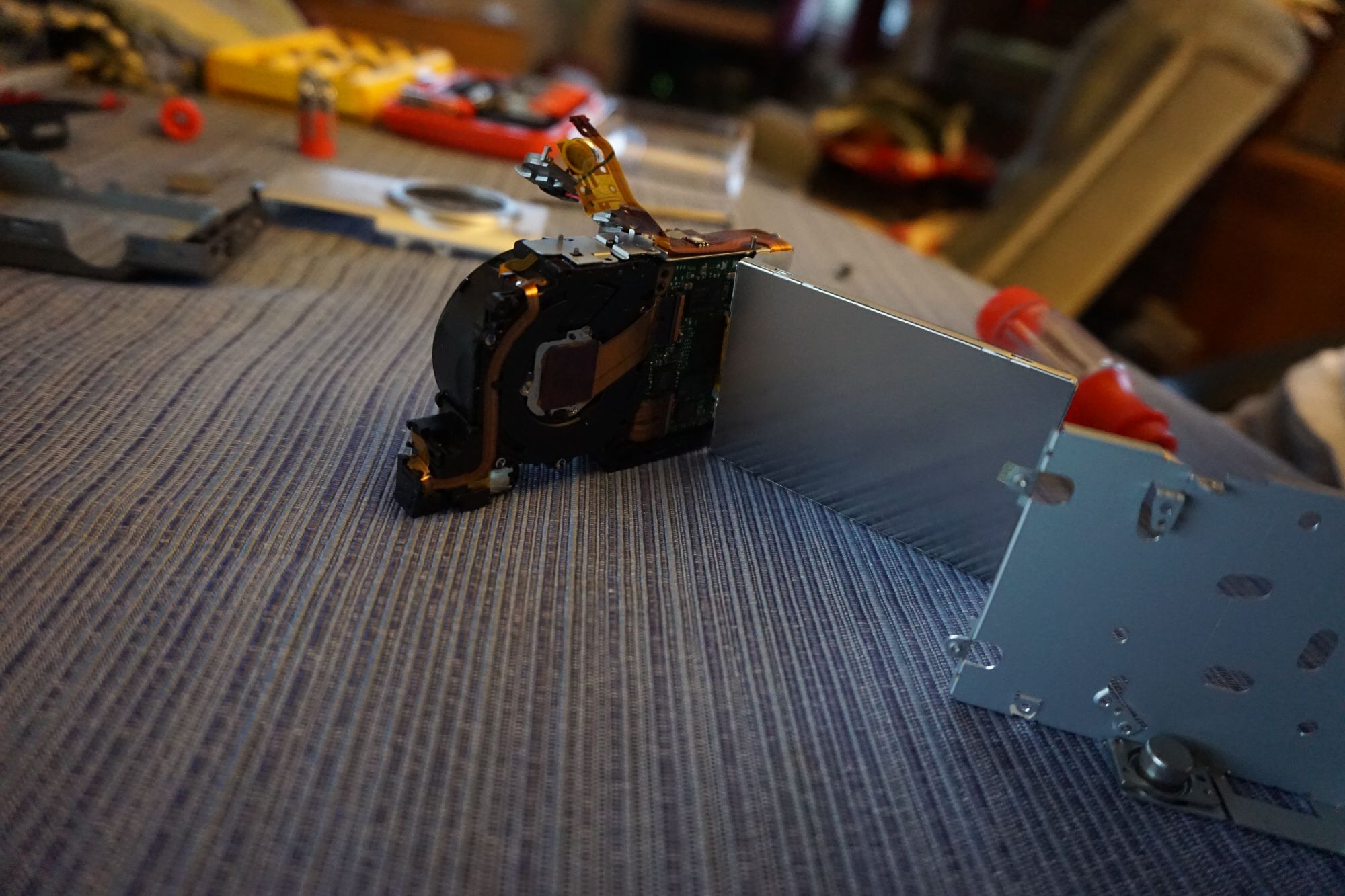
Once the bracket is out, you now have access to the back of the imager which is what you need. There are three screws (highlighted in red below) that attach the imager to the back of the lens assembly. The three screws are potted with dabs of epoxy that must be removed. This is the hardest part of the operation. Take some small screwdrivers and carefully pick away the epoxy. Try to clean as much of it away as you can. I got almost all of it and still had to do a little cleanup after removing the imager. Any left over could make it hard to reinstall the imager and you’d rather get it now than when the lens/imager is open to the elements.

Once the epoxy is all gone, clean the area up with canned air and cleaning brushes if you have some. Then mark the three screws with a sharpie. I put a single dot on the periphery of the head, overlapping onto the bracket below. You will need to be able to put them back exactly where they were before. Once they are marked, remove the screws, making sure to remember which one goes where as you don’t want to swap them around. Once they are removed, carefully pry up the imager. Make sure not to dislodge any washers shimming it underneath. Mine had one washer. I detached the flex cable leading to the imager so I could set it aside. DO NOT touch the surface of the sensor array. If you do you should carefully clean it (but just don’t!).
Almost there! Clean up a bit more epoxy if you need to and make sure to blow out any little bits left over. Once everything is clean, carefully pry out the rubber gasket where the imager was. Under this gasket is our target! A tiny piece of IR blocking glass. Pull that sucker out! Assembly is the reverse. Carefully put the gasket back in place. Reinstall the imager module being sure to put the screws in exactly as they were lining up your marks. Reconnect the imager flex cable. Reinstall the steel bracket and all the screws. Reinstall the button assembly. Reinstall the flash module and hook up the flex cable there too and the single screw. Once you are this spot (before putting the screen fully back) you can power back on the camera and try taking some test photos. If there are focus issues you might have to adjust the tension on the three imager screws (which are conveniently still accessible even with the bracket installed). If everything looks good, button her up!
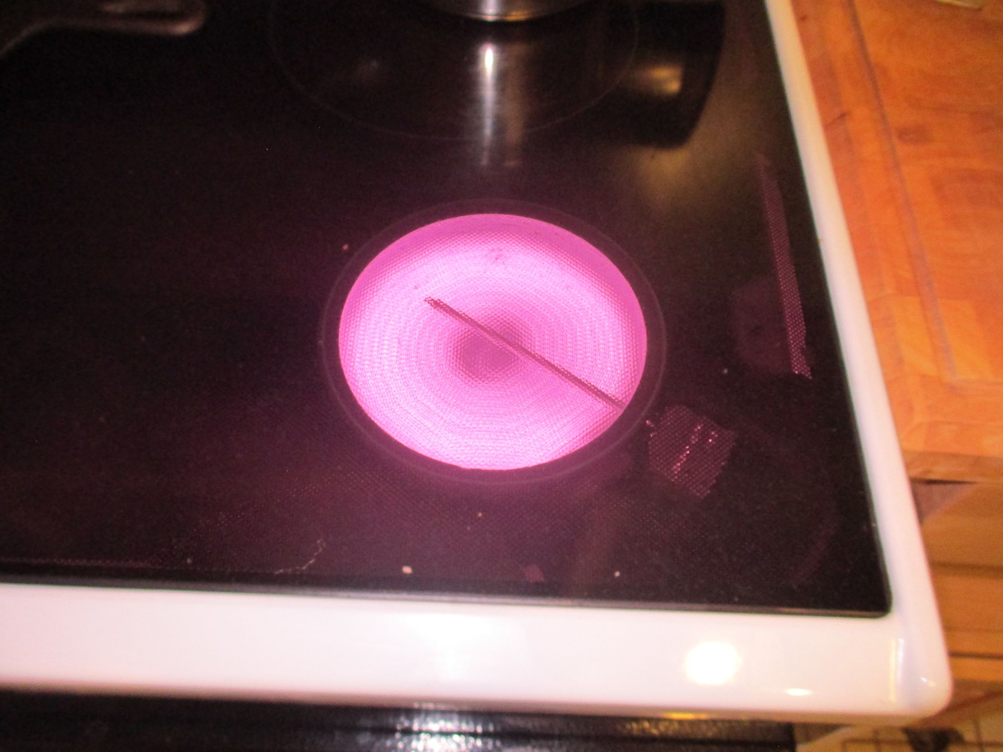
Here is a test photo of my stove (looked black to the naked eye):
Hopefully you didn’t get any particles inside the lens when you had it open!