I have a 2008 Tomos Streetmate moped. Great for getting around town. Like many mopeds, the tail light (and brake light) run off the unregulated voltage coming out of the alternator. This allows the lights to run even when the bike is idling (~9V), but also means that on high speed downhills the light could be seeing up to 20V. Since automotive light bulbs are designed for ~14V, it means the tail light blows out all the time. This is bad since when you are riding it is impossible to know and not having a light will make it a lot easier to get hit at night. The LED will not only be much brighter but will come on faster (~100mS) which gives other drivers just a tad more time to react before rear ending me!
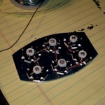
To fix all these issues I decided to construct a custom made LED tail light. DOT rated car and motorcycle tail lights use a 21W filament for the brake light and a 5W for the tail light. To this end I decided that 6 China made 3W red LEDs would fit the bill. I purchased them from an ebay seller called “ledtoplights”. Six of them ran about $15 (plus shipping!) Quality seemed fine, although I did resolder the LEDs onto the carrier boards. Since the LEDs are emitting only red light and the standard incandescent bulbs put out white light that is then filtered red, 18W worth of LEDs will be several times brighter than the old 21W bulb.
Since we already know the Moped power system has a highly variable voltage, it is important to drive the LEDs with a constant current supply designed for LEDs. A standard resistor will not be adequate for this application because of the high current and the variable input voltage. The six LEDs are wired in series and with 2.3v-2.8v forward drop per LED that means our series array is dropping 13.8-16.8V across it. This is typically more than the Moped’s power system puts out so having an LED driver that can step up the voltage will be necessary. After looking around a bit I decided to use an evaluation board for the Allegro A6265. This chip is a great device, supporting buck-boost power conversion and able to drive up to 10 LEDs in series. It also looked like it will have no trouble driving the 6 LEDs from a supply anywhere from ~7V up to 50V. At some point I may construct a PCB based on this board but in the mean time I plan to just tape up the eval board and stash it under my moped seat.
My original design was to make up an aluminum plate which would sit inside the factory reflector. This was WAY too hot so we scrapped it. I made up an aluminum plate (.125″ thick) sized to match the back of the Tomos’s tail light lens perfectly. This could then be sandwiched between the factory red lens and the light cutout in the rear fender, taking the place of the factory bulb holder and reflector. The left the back of the plate exposed to air (right behind the rear tire). The LED’s were mounted to this plate with heat sink grease and 4-40 hardware, then wired up for testing. This looked great and mounted up perfectly to the moped!
I had hoped that the thick aluminum plate would be enough heat sinking to keep the LED’s cool with the air behind it, but this was not the case. At full power the LEDs quickly got hot enough that brightness was visibly reduced. To solve this issue I cut the corners off an old AMD Athlon heat sink and bolted it to the back of the plate. This heat sink is designed to dissipate at least 50W worth of heat from a CPU (albeit with a fan blowing over it constantly) but seems to be enough cooling area! With this massive heat sink attached the LEDs now don’t get hot at all. This big heat sink sits in the recessed part of the plastic fender and ends up right behind the rear tire where it will get plenty of airflow (and water and dirt… hopefully it will survive).
-
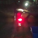
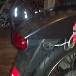
- Original incandescent tail light
-
- Original incandescent tail light
-
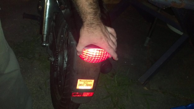
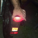
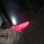
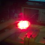
- New LED tail light installed
-
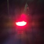
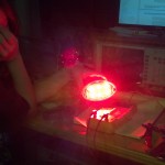
- New LED tail light, easy to see how bright it is but hard to compare.
-
- Temporarily installed tail light with wiring hanging off the side.
-
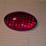
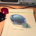
- The stock tail light lens on the Tomos Streetmate.
-
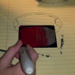
- Tracing the stock tail light lens onto a template and then marking on a sheet of aluminum.
-

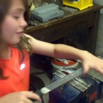
- Avi using the hacksaw to cut out the plate.
-
- Filing to size.
-
- The stock incandescent reflector and bulb holder. The plate takes the place of this.
-
- My original design had the LED’s mounted to a plate which would sit inside the original reflector. This ran way too hot.
-
- The original design had the LED’s mounted to a plate which would sit inside the original reflector (way too hot!)
-

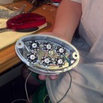
- Avi showing off our first attempt
-
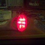
- LED tail light bench test (original design)
-
- LED tail bench test (original design)
-
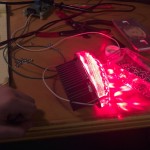
- Final design with larger plate and huge Athlon heat sink
-
- Bench test of the final design.
The only remaining task is to figure out how to get the tail light to vary in brightness depending on whether just the running light is on or if I am hitting the brakes. The A6265 eval board has a potentiometer which can be turned to vary the current through the LED string (up to a maximum of around 1A). It also has a spot on the board which if pulled up to 5V causes the LED to go to full brightness. My plan was to power the eval board through two high power diodes, each hooked to the brake light line and running light line respectively. This would give the board power if either the running light or brake light was on. I will set the potentiometer to the brightness desired for the running light. Then to increase the brightness when the brakes are hit I would run the brake light power line through another diode and a resistor. The resistor would then end with the brightness input pin, and have a 5v zener diode running to ground. The zener will regulate the voltage to 5v (down from the brake light voltage which could be fairly high). My first attempt at this failed. I used some 9A rated power diodes (more than required), but they had such a high reverse current that the voltage from the running lights would bleed back through the brake light diode and cause the brightness to go to maximum. I tried using two diodes in series but this was still not enough blocking. I am now waiting on some more appropriately sized diodes with less reverse leakage! In the meantime I wired it to be powered off the running lights and to increase brightness when the brakes are pressed. This means the brake lights won’t work if the running lights are off but I always ride with the running lights anyways.
Now I just need to find time to install it.